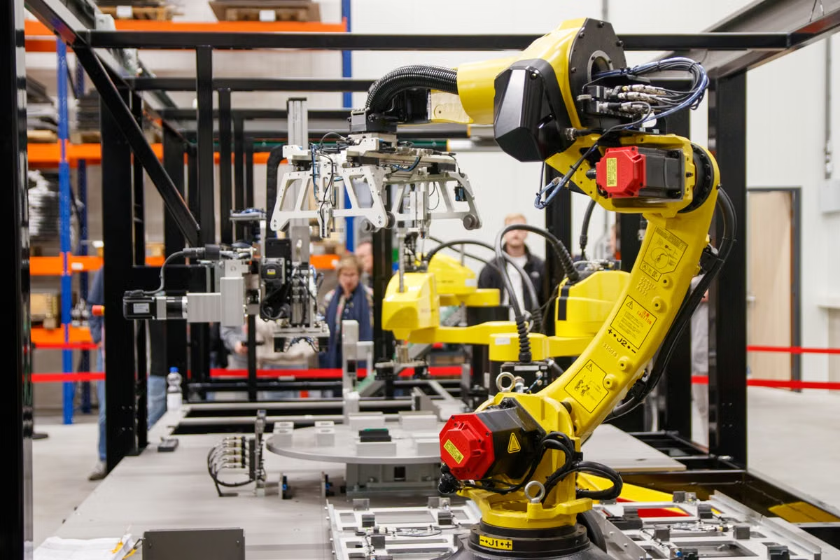
The safer way to integrate RealSense D585 Pro for robotic picking is to validate the complete chain—mounting and calibration, depth data, coordinate transforms, and grasp trials—in that order. This applies when the camera’s officially documented interfaces and operating conditions match the target cell; it does not make the camera plug-and-play with every robot.
Robot software engineers can use this sequence to connect RGB-D perception to a picking pipeline.
Vision integrators can use it to plan calibration and coordinate-frame checks.
Automation leads can use it to assess commissioning work before adding a camera to an existing cell.
Check product and cell readiness before installation
As of October 2, 2026, RealSense has announced D585 Pro product information. Confirm the current specifications, available software interfaces, operating-system support, and supply status on the official D585 Pro announcement and product page. These sources are the boundary for product claims; neither an announcement nor a camera specification proves that a particular robot, controller, or picking application is compatible.
Last updated October 2, 2026; product status and setup references checked against RealSense’s official announcement, product page, and supported operating systems list. Recheck those references before commissioning if the camera revision, SDK, driver, or host system changes.
Before selecting a mount, record the job conditions that determine whether the camera can see useful depth data:
- Target geometry: note the smallest parts, reflective or dark surfaces, transparent areas, likely orientations, and whether parts overlap in the bin.
- Working space: identify the camera-to-pick region distance, approach and retreat paths, and any obstructions that can enter the field of view. Compare the real installation with the currently published product information; do not substitute assumed values.
- Lighting and background: observe the actual cell under production lighting, including changes from shadows, glare, nearby equipment, and ambient light.
- Robot and controller: confirm what image transport, middleware, network, and command path the robot stack accepts. Check whether the controller can consume the proposed pose representation and whether motion planning handles the cell’s obstacles.
- Software baseline: record the host operating system, SDK and driver versions, ROS packages if used, and camera firmware. Compare the intended combination with RealSense’s current operating-system support information before building the integration around it.
If the official documentation does not list a required interface or software combination, treat it as unverified. Test it in a controlled setup before designing the production cell around it.
Choose the camera arrangement that fits the picking task
A fixed camera above or beside a work area and a camera mounted on the robot end effector solve different integration problems. The right choice depends on whether the scene is stable, whether the robot can view occluded parts from more than one pose, and whether the added moving-camera calibration is justified.
- Fixed camera: the camera remains still while the robot moves. Its pose relative to the robot base is normally established during commissioning and needs checking if the mount moves. This arrangement can simplify repeatable viewing of a defined pick region, but parts or robot tooling may hide the target.
- Eye-in-hand camera: the camera moves with the robot. The system can observe the scene from different poses, which may help with occlusion, but camera-to-tool calibration and pose updates become part of the perception-to-motion chain. A camera view that was valid at one arm pose cannot be treated as though the camera were fixed.
What changes between an end-effector camera and a fixed station camera?
With a fixed camera, the image-to-robot relationship depends on a stable camera mount and a verified transform from the camera frame to the robot base. With an eye-in-hand camera, the transform from camera to tool must also be known, and the robot’s current tool pose is needed to express an observed target in the base frame.
That difference affects both commissioning and failure diagnosis. If a fixed-camera pick is consistently offset, inspect the mount and camera-to-base transform before changing grasp offsets. If an eye-in-hand pick changes with robot pose, check the hand-eye calibration and the pose timestamp used by the transform chain. In either arrangement, document frame names and transform direction; a mathematically valid transform applied in the wrong direction still produces an invalid target pose.
Prepare calibration data and define the frame chain
RGB-D camera calibration is not a value to copy from a sample project. Intrinsic parameters describe the camera’s image geometry, while extrinsic parameters describe relationships between coordinate frames. Both must be obtained or verified for the actual camera, lens configuration, mounting arrangement, and software path in use.
Use the OpenCV camera calibration tutorial as a reference for the calibration process, and the RealSense SDK projection and coordinate documentation for the SDK’s treatment of projection and coordinate relationships. Keep the calibration output with the camera identity, mounting record, software baseline, and date of capture so later changes can be traced.
For a fixed camera, a typical transform chain is:
robot base ← camera ← observed target
For an eye-in-hand setup, it commonly includes the tool frame:
robot base ← tool ← camera ← observed target
These expressions describe the required relationships, not a universal implementation. The actual frame names and transform directions must match the robot software and camera pipeline. In either case, the output sent to the motion planner must use the frame the planner expects.
Which calibration checks belong before the first pick?
Record the camera intrinsics, camera mounting pose, robot base frame, tool frame where applicable, and the method used to estimate each transform. Then place a known target at reachable points in the work area and compare the transformed robot-frame position with the target’s physical location. Use targets spread across the working region rather than relying on a single central observation; a transform can appear plausible at one position while showing a growing error elsewhere.
The RealSense SDK projection guide is relevant when mapping image pixels and depth into camera coordinates. It does not provide the cell-specific camera-to-base or hand-eye calibration. Those values must come from measurements of the installed camera and robot.
Calibration warning: Do not paste example intrinsics, extrinsics, or robot poses into a production configuration. A changed mount, tool, image stream, or frame convention can invalidate the relationship even when the software still starts without an error.
Inspect depth before connecting grasp commands
A visually convincing color image does not guarantee usable depth at the pick point. First inspect the depth output over the actual target region, including representative parts, backgrounds, and orientations. Look for missing pixels, abrupt changes at object boundaries, unstable readings, and areas where foreground and background merge.
The RealSense SDK API documentation describes access to depth data. Use the documented stream and API behavior to confirm that the application is reading the intended data, applying the correct units and frame, and handling invalid values explicitly. Do not allow missing depth to silently become a plausible surface point in the grasp pipeline.
What should be checked when depth has holes or jumps?
Start by separating a camera observation issue from a processing or integration issue:
- Check the raw view and depth output together. Confirm whether the gap is present in the sensor output or appears only after application processing.
- Inspect the target and background. Reflective, dark, transparent, narrow, or partially hidden surfaces can be difficult for depth-based perception. Test the actual production parts rather than a convenient stand-in.
- Recheck distance and viewing angle. Compare the installation with the official operating guidance, and observe whether the defect moves or changes when the part or camera position changes.
- Inspect lighting and obstructions. Look for glare, shadows, vibration, protective covers, or tooling that crosses the camera view.
- Trace the processing chain. Check stream selection, synchronization, invalid-value handling, alignment, filtering, and any conversion between camera and application coordinates.
The RealSense post-processing documentation describes available depth filters. Filtering can change the data used by the application; it cannot restore reliable geometry where the underlying observation is absent or ambiguous. Keep a record of raw and processed samples so a change in filter settings can be evaluated against the actual failure, not just against a smoother-looking image.
Use representative objects to decide whether the depth or point-cloud result supports the task. If the target’s usable surface is incomplete or unstable at the planned grasp point, first change the viewing geometry, target presentation, or sensing approach. Do not compensate for unreliable depth by increasing grasp offsets without identifying the cause.
Verify transforms and robot motion as separate stages
Once camera-frame target positions are stable, verify the transform chain before allowing automatic picking. A simple test is to observe a known target, convert its position into the robot base frame, and compare that result with a separately established physical reference. Repeat at other reachable locations and camera poses relevant to the task.
For an eye-in-hand arrangement, capture the robot pose associated with the image and apply the camera-to-tool and tool-to-base relationships consistently. For a fixed camera, verify the camera-to-base relationship and confirm that the camera did not shift after calibration. If results vary with robot pose when the camera is fixed, investigate timestamps, frame IDs, and software transform handling before adjusting the camera mount.
Only after the coordinate check passes should the robot motion be tested. A valid target point is not automatically a safe or reachable grasp. The planner must account for the tool orientation, approach direction, robot limits, nearby parts, bin walls, and other equipment. The MoveIt planning-scene documentation explains how collision objects and planning-scene information support motion planning. The cell’s actual collision model and safety controls still need to be validated with the robot team.
For a ROS-based integration, compare the message frames and camera configuration against the official RealSense ROS package documentation. Confirm that the image, depth, and transform data consumed by the robot application refer to the same camera setup and time context. A topic being available does not establish that its frame, units, or timing are correct for a pick.
Run grasp trials before enabling production behavior
Test the whole closed loop with representative parts and placements, starting with supervised motion. A useful trial record links each observation to its result: detected target, estimated pose, planned motion, gripper action, and whether the part was actually picked and placed. Preserve failures as well as successes; a log containing only successful cycles hides the conditions that matter for recovery.
Include changes in part orientation, overlap, partial occlusion, and background appearance that reflect the real work. If a grasp fails, classify the failure before tuning:
- Detection failure: the object was missed, merged with another object, or assigned the wrong identity.
- Depth or pose failure: the target was detected but its three-dimensional position or orientation was not trustworthy.
- Transform failure: the camera-frame estimate did not map correctly into the robot frame.
- Planning failure: the pose was valid but unreachable, in collision, or incompatible with the approach direction.
- Grip or handoff failure: the planned motion completed, but the tool did not acquire, retain, or release the part as intended.
Change one relevant part of the pipeline at a time and rerun the affected cases. If the task changes to smaller, more reflective, more overlapped, or more frequently occluded parts, repeat the perception and grasp validation; success on an earlier object set does not establish performance on the new one.
Use this decision list to decide what to change next:
- If depth is continuous at the intended grasp surface and the target pose maps correctly to the robot base, then proceed to supervised planning and grasp trials; otherwise return to viewing geometry, depth inspection, or calibration.
- If fixed-camera results drift after maintenance or contact with the mount, then inspect the mount and repeat the camera-to-base check; otherwise continue monitoring the stored reference.
- If an eye-in-hand target shifts with arm pose, then verify hand-eye calibration and the robot pose paired with the image; otherwise investigate detection, timing, and tool constraints.
- If the pose is valid but motion planning rejects it, then review reachability, collision geometry, and approach constraints; otherwise investigate grasp planning or gripper behavior.
- If new parts or occlusion patterns are outside the tested set, then add representative samples and retest before changing production behavior; otherwise retain the tested configuration and its records.
Keep the installation verifiable after commissioning
A picking system can drift even when the perception code has not changed. Establish a repeatable inspection routine for lens cleanliness, mount stability, calibration references, software changes, and saved failure data. Define who owns each check: the robot team should cover motion and tool constraints, the vision team should cover image and depth processing, and the production team should report changes to parts, lighting, or fixtures.
Keep logs that help distinguish a perception issue from a robot or process issue. Depending on the system’s data policy, retain representative color and depth frames, detected poses, transform values, robot state, planner outcome, and grasp result. Protect image data according to site rules, and make sure the retained files can be matched to the software and calibration record that produced them.
After a camera move, tool change, software update, filter adjustment, or significant scene change, repeat the checks affected by that change. A driver update may require stream and depth verification; a mount adjustment requires recalibration; a gripper change requires new grasp and collision checks. Avoid treating a clean application startup as proof that the complete picking chain remains valid.
For deployment planning beyond the camera itself, the Zutcloud help center can be used to review service and account information, while the Zutcloud contact page provides a route for questions about available options.
Choose compute for the validation phase, not as a substitute for robot control
A local workstation already connected to the robot may be the right place for time-sensitive perception and motion integration. Its drawbacks are that engineering tasks can compete for the same machine, environment changes can make tests harder to reproduce, and tying up a development computer can interrupt other work. A remote or rented Mac is not a replacement for a validated robot controller, and the D585 Pro’s compatibility with a particular Mac, SDK, and connection path must be confirmed in current official documentation before it is selected.
For a temporary, non-real-time evaluation that specifically needs a Mac environment, renting a Mac from Zutcloud can be a better experience than dedicating or purchasing another machine: the evaluation can stay separate from the production robot controller and the team’s daily workstation. That option is not a fit when the cell requires direct physical interfaces, deterministic local control, or sustained production workloads. Review the Zutcloud Mac mini options only after confirming the required operating system, SDK, camera interface, and remote-access workflow.
Set Up a Remote Mac for Robot Vision Development
Rent a dedicated Apple Silicon Mac from Zutcloud to build and refine your vision-processing software.
Use native CPU, GPU, and Neural Engine resources to evaluate compatible AI workloads during development. Order now